Jump to a question in this guide
- The furnace is running. Why is this room still cold?
- First identify what actually heats this room
- Learn the supply register and the return grille
- Warm air and enough air are different questions
- Meet the circulating blower and its filter
- A closed bedroom door can change the return route
- Follow the trunk, branch, boot and register
- The room may be losing heat faster than you expect
- The thermostat speaks for its own location
- Make a short, comparable comfort record
- Keep ordinary observations separate from service work
- Ask for measurements that answer different questions
- Compare repairs by the mechanism they change
- Leave with a clear proposal and a useful next question
- Follow the complete supply, room and return route before assuming the heater is too small.
- Separate moving enough air from the room’s heat loss and the thermostat’s location.
- Use safe ordinary observations, then match the professional assessment and repair to the question.
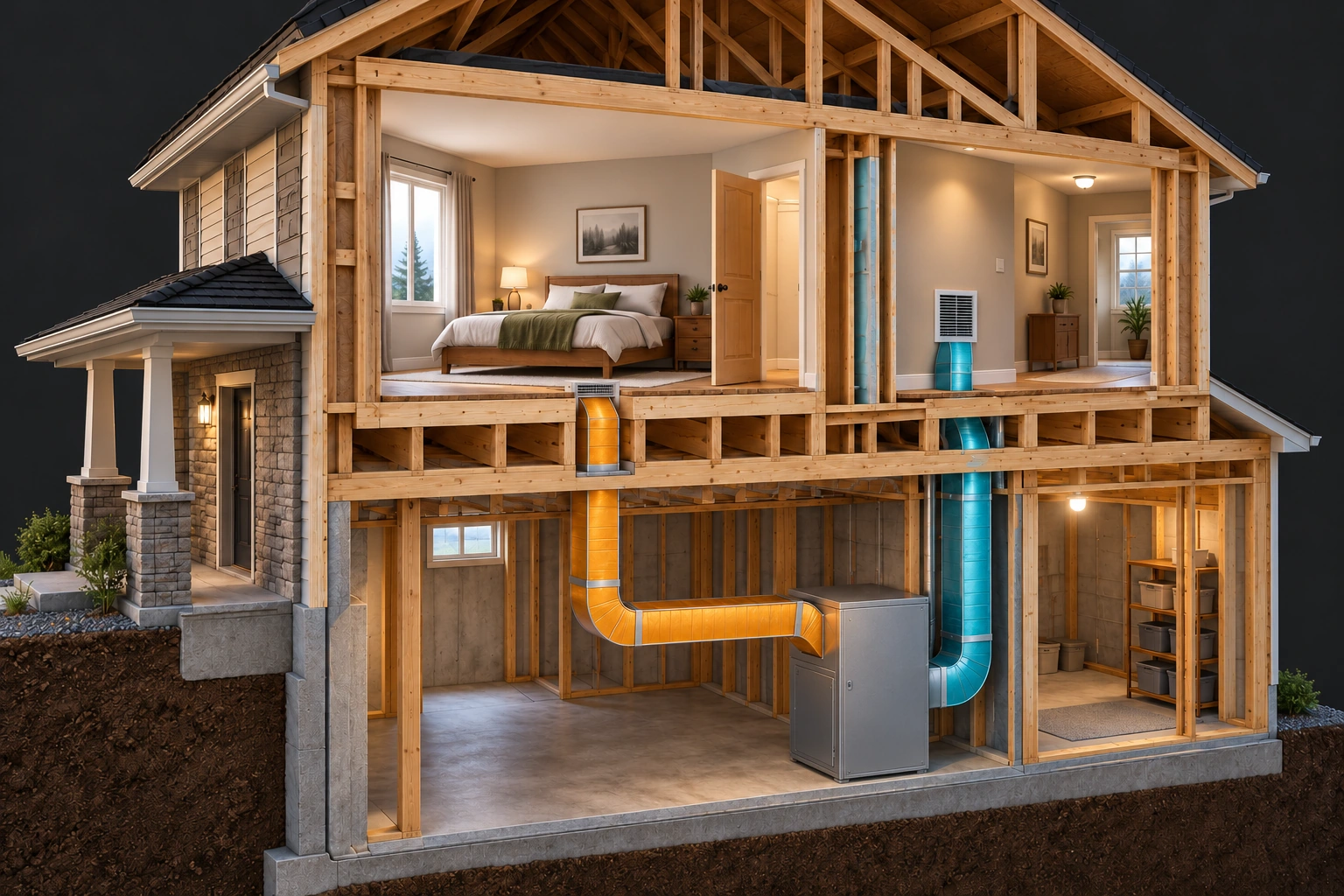
Supply duct, bedroom and hallway return. The open doorway links the occupied room to the shared return route in this example. Colours distinguish household-air routes; no temperature, flow, fuel or combustion route is established.
About this illustration
11 picture lessons appear beside the questions in this guide. Use them to understand the explanation, then consider what it means for your home.
The furnace is running. Why is this room still cold?
You can hear the heating come on, the hallway feels comfortable, and one bedroom still needs an extra blanket. Before buying a bigger furnace or a booster fan, follow the route that serves that room. Heat has to reach it, and the room has to retain enough of that heat. A problem on either side can create the same complaint.
The room is part of a complete circulation route
Supply duct, bedroom and hallway return. The open doorway links the occupied room to the shared return route in this example. Colours distinguish household-air routes; no temperature, flow, fuel or combustion route is established.
Explore the labelled parts
- Supply route
The amber duct connects the closed cabinet with a bedroom supply register. The cutaway makes this example route visible; its colour is a teaching accent, not a temperature reading.
- Doorway and room
The bedroom doorway is open to the hall. Household air can use an available room-to-return path; actual closed-door performance needs its own assessment.
- Return route
The visible hallway grille and teal duct form the illustrated return connection toward the cabinet. The return is household circulation, not a claimed outdoor-air intake or flue.
- Closed equipment
The cabinet remains closed. Fuel, internal components, capacity, concealed connections, code compliance and safe operation are outside this architectural view.
In a forced-air system, a circulating blower moves household air through the heating equipment and supply ducts. Branch ducts carry it toward individual rooms. Air enters through supply registers, moves through the occupied space, and returns through an available route to the equipment. The first picture follows one complete conceptual loop, including the doorway and return grille that are easy to overlook.
The warm jet at a register is only one part of that loop. A bedroom with a small delivery of very warm air may still struggle. Another room may receive adequate air but lose heat rapidly through its outside surfaces or air leaks. Those possibilities can occur together; a furnace service receipt does not distinguish them.
Begin with the pattern: one room, one floor or the whole home? Note whether the change followed a renovation, equipment replacement, filter change or new furniture arrangement. You are describing when comfort changed, not deciding which hidden component failed. That description helps the person assessing the system choose the right work.
Sources for this chapter
First identify what actually heats this room
A grille does not automatically mean furnace heat. A central gas or electric heating system can distribute heat through ducts; a ducted heat pump also uses an indoor coil and air-distribution system. Its heat source differs, while the need for suitable supply and return paths remains. Identify the actual system from existing equipment records and its manual rather than cabinet appearance.
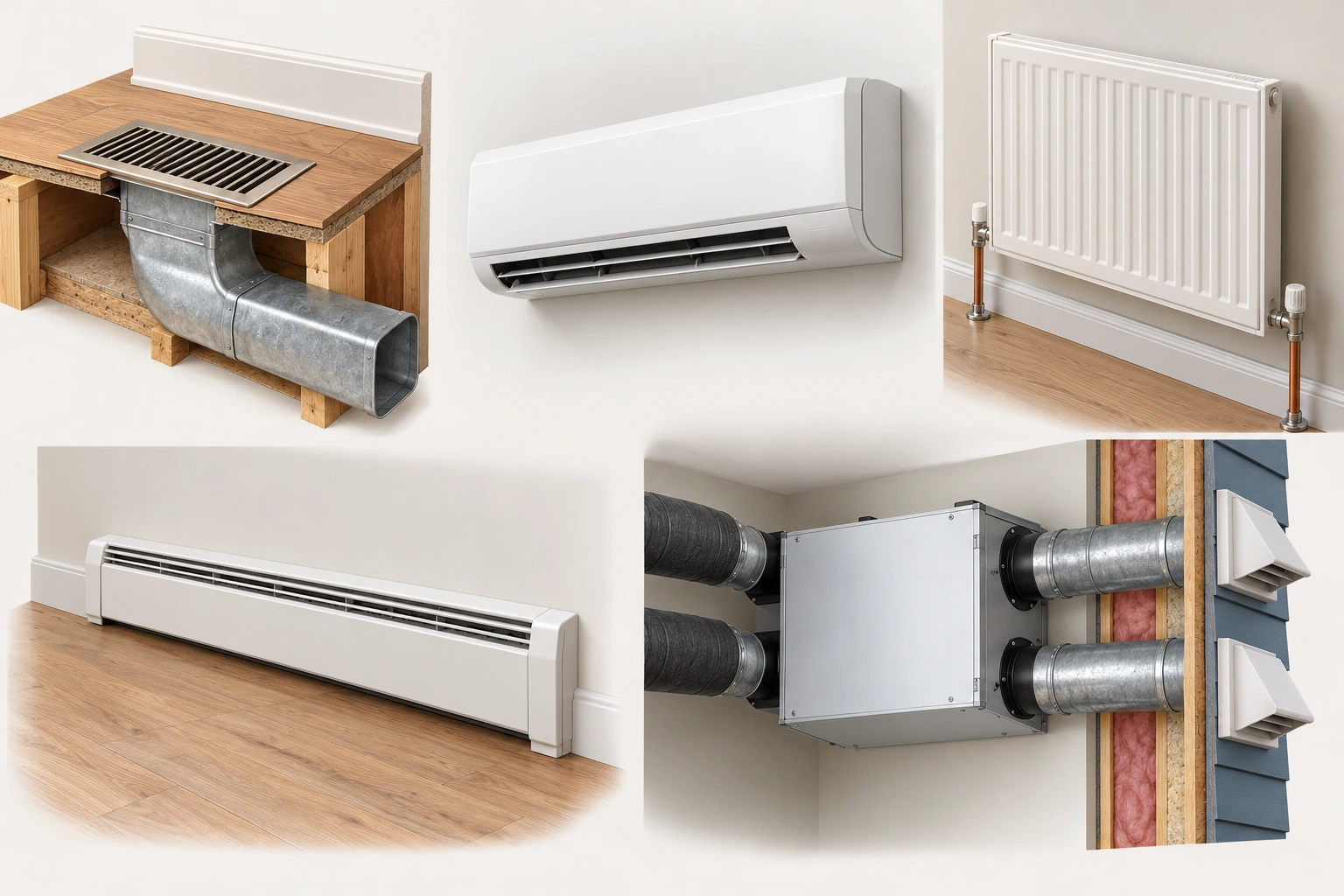
Four heat-delivery examples and a separate ventilation job
A supply register, ductless indoor head, water radiator and electric baseboard deliver heat in different ways. The ventilation unit has a separate job: exchanging indoor and outdoor air. These are recognition examples; equipment records and the actual installation identify which system serves the room. The cutaways and exterior connections are conceptual, not installation details.
Explore the labelled parts
- Supply register and duct boot
The grille and continuous duct boot show where household supply air reaches a room. Their appearance does not identify a furnace, fuel or ducted heat pump upstream.
- Ductless indoor head
This wall-mounted indoor unit exchanges heat with air in the space it serves. It does not use the pictured central room-supply branch.
- Water radiator and pipes
The two water connections belong to this radiator example. Heated water can also serve floor circuits or other emitters; follow the actual water-based system.
- Covered electric baseboard
The long covered room heater is the electric-baseboard example. Its heating job does not establish a central supply duct or a fresh-air connection.
- Ventilation unit and outdoor connections
The closed cabinet and separate indoor/outdoor ducts represent ventilation. Actual ventilation may use dedicated ducts or connect to heating-distribution ducts; this view establishes neither flow nor correct termination spacing.
NRCan distinguishes ducted heat pumps from ductless room units. A wall-mounted ductless unit circulates air in the space it serves without using the illustrated central room-duct loop. A heat pump can also supply a water-based system. The words heat pump identify a heat-transfer technology, not one universal arrangement of ducts.
Radiators, water-heated floors and electric baseboards need their own diagnosis. A pure radiator or electric-floor system does not acquire a central supply branch because a nearby ventilation grille exists. Follow the appropriate water-circuit, heated-floor or baseboard guide when those parts heat the room; do not apply duct remedies to them.
Fresh-air ventilation is another job. An HRV or ERV exchanges indoor and outdoor air and may connect to a forced-air system, but the household return duct in the pictures is not automatically an outdoor-air intake. Ask which equipment provides heating, circulation and ventilation when several systems share the home.
Which heat-delivery route belongs to this room?
- Central forced airA circulating blower and supply/return network distribute household air. Follow this room’s branch and return path. The heat source may be fuel, electric or a ducted heat pump. Which equipment and ducts serve this room?
- Ductless room heat pumpAn indoor unit exchanges heat with air in its served space. Identify the actual indoor unit and served rooms. The illustrated central duct loop may not apply. Which spaces is this unit intended to serve?
- Water-based emittersHeated water serves radiators, floors or other emitters. Use the hydronic circuit and control guide. A ventilation grille does not identify the room’s heat source. Which water circuit and emitter serve the room?
- Electric floor or baseboardRoom equipment supplies heat without the shown central supply branch. Use the actual equipment and control guide. Do not prescribe a return duct for an unrelated heating system. Which control and equipment heat this space?
- Fresh-air ventilationAn HRV/ERV or other arrangement exchanges indoor and outdoor air. Identify any connection to the heating distribution. Household circulation is not automatically outdoor-air supply. Which system handles ventilation?
These are recognition routes, not an exhaustive equipment classification or an assessment of a particular installation. Manufacturer and actual-system requirements remain specific.
Further reading: Natural Resources Canada · Keeping the Heat In, Section 9: Operating your house; Natural Resources Canada · Heating and cooling with a heat pump; Health Canada · Ventilation and the indoor environment.
Sources for this chapter
Learn the supply register and the return grille
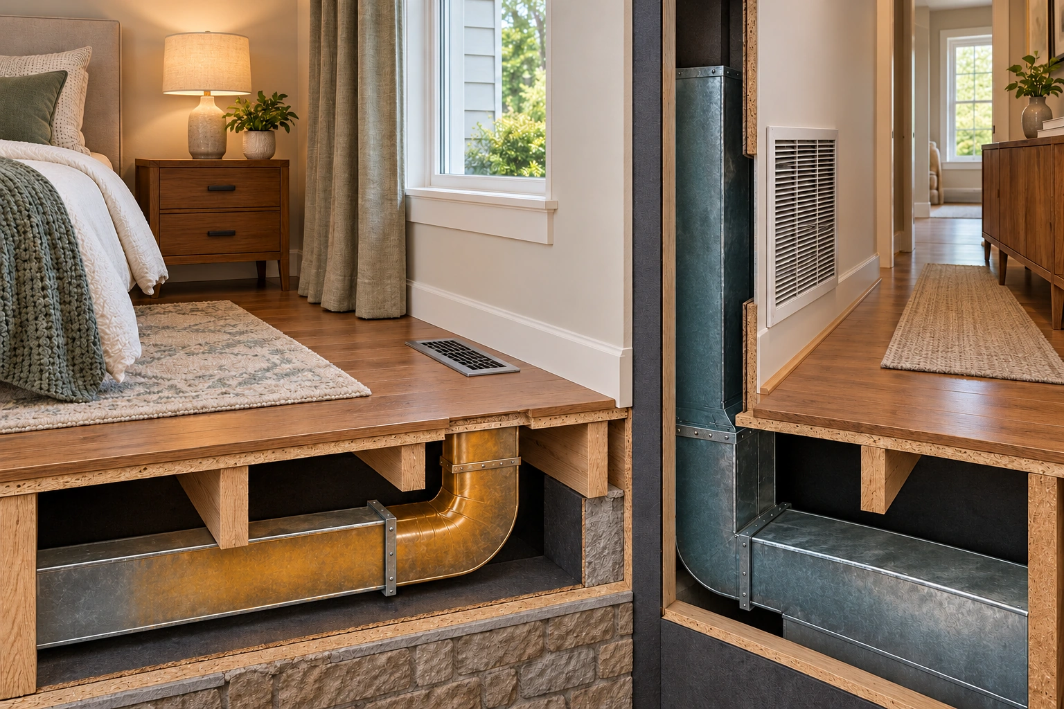
The supply register is the room outlet from a supply duct. Behind it, a boot connects the duct to the opening in the floor, wall or ceiling. A return grille is an inlet to a return route. Its job is to let household air travel back toward the circulating blower. The paired picture shows the different jobs and the hollow connections behind the visible faces.
Recognize the supply outlet and return inlet
Supply register and return grille. The cutaway reveals their separate duct connections and jobs. This familiar floor-and-wall arrangement is an example; face size or louvre pattern alone does not identify every installation.
Explore the labelled parts
- Floor supply register
The bedroom register opens above the connected supply boot. Keep its ordinary usable opening clear according to the actual system instructions.
- Boot and supply duct
The fitting changes the route from the branch duct toward the room opening. No measured delivery or universal fitting geometry is supplied.
- Wall return grille
The hall grille opens to the illustrated return connection. Grilles can have other locations and arrangements in real homes.
- Clear room openings
The rug and furnishings leave these two example openings unobstructed. No numeric clearance, balancing position or owner disassembly procedure is shown.
A floor register is a familiar supply example, and a larger hallway grille is a familiar return example. Their size, position or louvre pattern alone does not reliably identify every installation. Some rooms have their own ducted returns; others rely on a shared route outside the room. Existing plans or an HVAC assessment can clarify an uncertain opening.
Look for ordinary obstructions first. A rug over a floor outlet, a sofa against a return or storage piled in front of a grille changes the usable opening. Keep those routes unobstructed in accordance with the actual equipment instructions. This is different from removing grilles, reaching into ducts or adjusting hidden dampers.
Do not close a collection of registers to force all the heat upstairs. The equipment and duct network need appropriate overall airflow as well as room distribution. An improvement felt in one place does not show what happened at the blower, other branches or the cooling coil. Ask for a balancing assessment if distribution remains uneven.
Sources for this chapter
Warm air and enough air are different questions
Imagine a warm trickle beside a broad stream of moderately warm air. The temperature is not the only difference: the amount of moving air matters too. Heat carried by the airflow depends on both its rate and the temperature change through the system. Feeling a grille with your hand cannot measure either the full room delivery or the room heat loss.
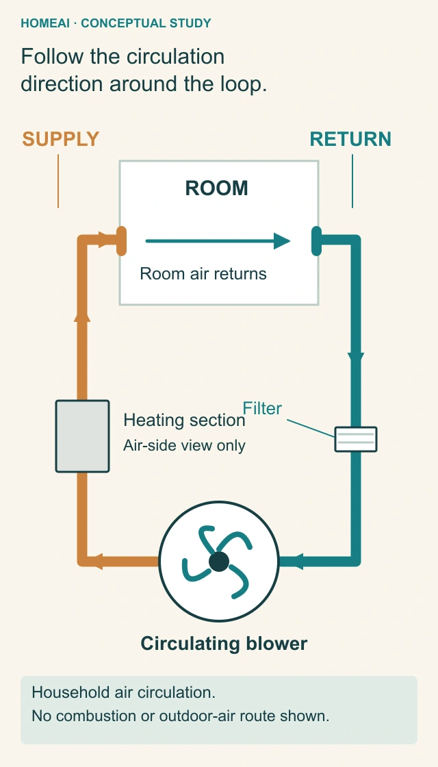
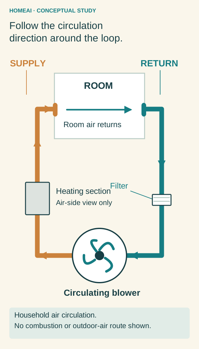
Follow the circulation direction around the loop.
Circulating blower, heating section, supply and return. The arrows trace one conceptual household-air loop. Combustion intake, flue exhaust and outdoor-air ventilation are separate systems and are not shown.
Explore the labelled parts
- Blower and supply
The circulating blower moves household air through this example heating section into the supply path and toward the room. Equipment arrangements vary; the air-side diagram does not identify a fuel or depict burner, refrigerant or electrical service work.
- Room and return
Air entering the room has an available route toward the return path. Real routes can include room return ducts or circulation through a doorway to a shared return. The diagram abstracts that room-to-return relationship; it does not show a hidden duct across every room.
- Filter in the loop
The illustrated external return filter is before the blower, matching the named manual example. Actual equipment instructions determine filter location, compatible specification and safe access; this drawing supplies no installation or panel-removal procedure.
- Separate systems
Household circulation is distinct from combustion-air supply, flue exhaust and outdoor-air ventilation. Those routes are omitted entirely. Arrows show conceptual direction, not measured airflow, temperature, pressure, fuel safety or a property finding.
The blower supplies a pressure difference that moves air through the network. Duct lengths, bends, fittings, filters and openings resist that movement. The resulting flow depends on how the actual fan and connected system work together. A noisy register is not a calibrated flow meter, and a quiet one is not proof of adequate delivery.
Two branches can therefore behave differently even when connected to the same equipment. One may have a longer route, a restriction or a leak; another room may have a less suitable return route. Those are investigation possibilities rather than findings from a picture. Useful measurements identify the room, operating mode and conditions being assessed.
NRCan also cautions that heat-pump distribution can differ from furnace operation: a ducted heat pump may deliver more air at a lower temperature. Do not judge every heating mode against the sensation of an older furnace. Have the provider compare the actual equipment requirements and duct capacity instead of promising that hotter air is always better.
Follow the circulation direction around the loop.
Circulating blower, heating section, supply and return. The arrows trace one conceptual household-air loop. Combustion intake, flue exhaust and outdoor-air ventilation are separate systems and are not shown.
- Blower and supply
- The circulating blower moves household air through this example heating section into the supply path and toward the room. Equipment arrangements vary; the air-side diagram does not identify a fuel or depict burner, refrigerant or electrical service work.
- Room and return
- Air entering the room has an available route toward the return path. Real routes can include room return ducts or circulation through a doorway to a shared return. The diagram abstracts that room-to-return relationship; it does not show a hidden duct across every room.
- Filter in the loop
- The illustrated external return filter is before the blower, matching the named manual example. Actual equipment instructions determine filter location, compatible specification and safe access; this drawing supplies no installation or panel-removal procedure.
- Separate systems
- Household circulation is distinct from combustion-air supply, flue exhaust and outdoor-air ventilation. Those routes are omitted entirely. Arrows show conceptual direction, not measured airflow, temperature, pressure, fuel safety or a property finding.
Read all the diagram text
- HOMEAI · CONCEPTUAL STUDY
- Follow the circulation direction around the loop.
- ROOM
- Room air returns
- SUPPLY
- RETURN
- Heating section
- Air-side view only
- Filter
- Circulating blower
- Household air circulation. No combustion or outdoor-air route shown.
Sources for this chapter
Meet the circulating blower and its filter
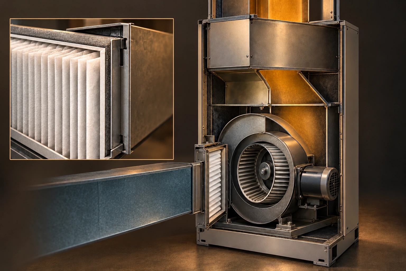
The circulating blower is the large fan that moves household air. In the conceptual cutaway, air passes through an external fitted filter before reaching the blower inlet; the scroll-shaped housing directs the air toward its outlet. The heating compartment remains closed and unshown. This picture explains parts, not a request to remove a cabinet panel.
Filter, circulating blower and outlet
External filter rack and circulating blower. The inset enlarges the filter frame and rack relationship. This is a conceptual anatomy view; it supplies no safe panel-removal procedure, installed filter specification or combustion assessment.
Explore the labelled parts
- External filter example
The illustrated filter is before the blower. The named manual shows an external arrangement, while actual equipment instructions determine location, compatible size, type and direction.
- Filter edge inset
The enlarged frame and rack identify where fit is relevant. It supplies no measured bypass, pressure drop or actual installed defect.
- Circulating blower
The wheel, housing and motor are the household-air mover in this example. Do not infer that a fuel-burning system’s separate combustion fan or flue is shown.
- Outlet and closed heating section
The housing directs air toward the outlet above. Colour only distinguishes the illustrated route; burner, refrigerant, wiring and heating performance are not explained or tested by this picture.
A fuel-burning furnace can also contain a separate combustion-related fan. It has a different job from the household circulating blower. The named Carrier manual, edition June 2020, shows those separate parts in one specific furnace family. Its arrangement is an anatomy example, not proof of the fuel, parts or approved configuration in your home.
A filter captures material while air passes through its media. It also adds resistance. A dirty filter, a different filter specification or poor edge fit raises different questions: resistance through the media and air bypassing the intended media are not the same mechanism. The close-up shows why the frame and rack matter as well as the pleats.
Use only the filter size, type and direction required by the actual equipment instructions. Follow a homeowner filter procedure only where the manual identifies safe access; do not open unfamiliar service panels to find one. If the correct filter is unclear, ask the service provider. The filter guide explains ratings, fit and pressure-drop questions in more detail.
Some blowers can adjust their operation as system resistance changes, but that is not permission to make the air path more restrictive. NRCan notes that some electronically controlled motors can use more power while responding to resistance. Ask about the installed fan and measured operating conditions rather than treating a newer motor as a cure for any duct problem.
Sources for this chapter
A closed bedroom door can change the return route
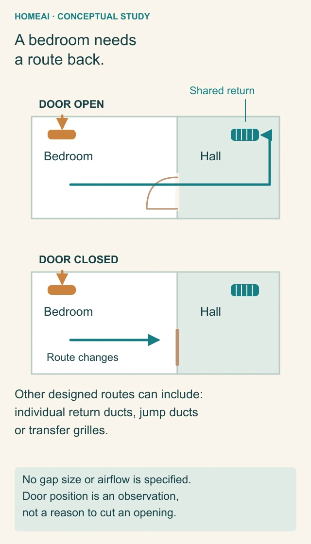
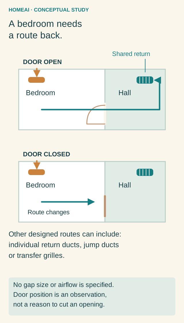
Supply air entering a bedroom needs a way out of the room as part of the circulation loop. With the door open, the doorway may provide a route toward a hallway return. Closing the door can change that route. A room with its own suitable return arrangement may behave differently from the example without one.
A bedroom needs a route back.
Bedroom doorway and shared return. Closing the door can change the available return route. Existing room returns or other designed paths can change the picture; no alteration is prescribed.
Explore the labelled parts
- Supply to the bedroom
The amber opening marks a conceptual room supply. Household air entering the room needs an available route out as part of the circulation loop.
- Shared hallway return
The teal grille represents a return outside this example room. With the door open, the doorway can connect the room to that shared route. The arrows are conceptual and show no measured quantity or pressure.
- Door closed
Closing this doorway changes the available path. This does not show that every closed bedroom is defective: an actual room can have its own return duct or another designed route. Record ordinary door position and the associated comfort pattern.
- Designed alternatives
PNNL describes individual return ducts, jump ducts and transfer grilles as possible designed paths. The US mechanism examples supply no Canadian installation dimensions, approval or owner cutting instruction. Have the actual route and any alteration assessed.
The paired plan shows the same supply and shared hallway return with two door positions. It does not show that every closed bedroom has a defect. Air paths and pressure differences depend on the whole installation, including existing return ducts and transfer routes. A door-position observation alone cannot identify a missing duct or prescribe an opening.
US Department of Energy-funded PNNL guidance describes individual ducted returns, jump ducts and transfer grilles as designed ways to provide return paths. Those are mechanism examples, not Canadian code details or a shopping list for cutting a finished house. Fire, acoustic, privacy and building requirements need the appropriate local design review.
Record the door position people normally use and the comfort pattern that accompanies it. Do not use sleeping with the door open as a prescribed fix, or cut a door or wall from this illustration. Ask the assessor to explain the actual return path, the measurements supporting a concern and the implications of the proposed alteration.
A bedroom needs a route back.
Bedroom doorway and shared return. Closing the door can change the available return route. Existing room returns or other designed paths can change the picture; no alteration is prescribed.
- Supply to the bedroom
- The amber opening marks a conceptual room supply. Household air entering the room needs an available route out as part of the circulation loop.
- Shared hallway return
- The teal grille represents a return outside this example room. With the door open, the doorway can connect the room to that shared route. The arrows are conceptual and show no measured quantity or pressure.
- Door closed
- Closing this doorway changes the available path. This does not show that every closed bedroom is defective: an actual room can have its own return duct or another designed route. Record ordinary door position and the associated comfort pattern.
- Designed alternatives
- PNNL describes individual return ducts, jump ducts and transfer grilles as possible designed paths. The US mechanism examples supply no Canadian installation dimensions, approval or owner cutting instruction. Have the actual route and any alteration assessed.
Read all the diagram text
- HOMEAI · CONCEPTUAL STUDY
- A bedroom needs a route back.
- DOOR OPEN
- DOOR CLOSED
- Bedroom
- Hall
- Shared return
- Route changes
- Other designed routes can include: individual return ducts, jump ducts or transfer grilles.
- No gap size or airflow is specified. Door position is an observation, not a reason to cut an opening.
Sources for this chapter
Follow the trunk, branch, boot and register
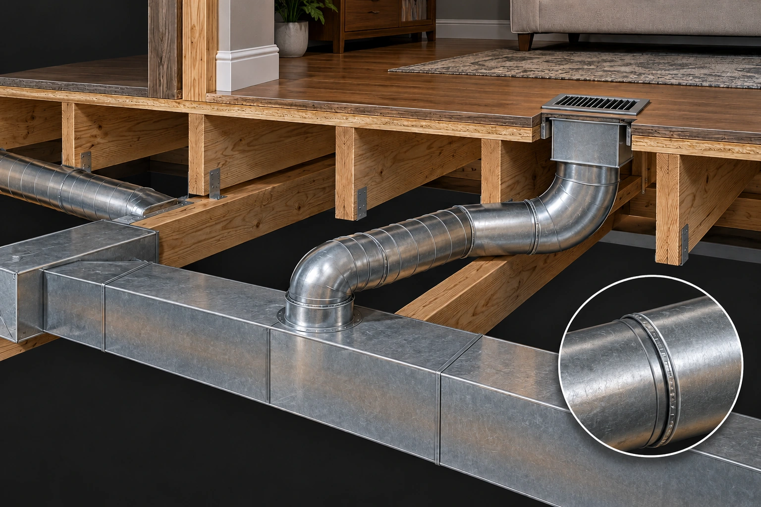
A supply trunk is the larger shared duct. A takeoff connects a smaller branch to it. That branch follows a route to the room, and a boot changes its shape or direction at the register. The picture keeps these connections visible so a complaint about the bedroom can be discussed as a route rather than an anonymous vent.
Trace a supply branch to its room
Supply trunk, takeoff, branch and register boot. These recognizable connections explain the room’s route. The inset identifies a joint; it does not prove airtightness, support adequacy or required repair.
Explore the labelled parts
- Shared trunk
The larger rectangular duct is the common supply route in this illustration. Another branch continues outside the picture.
- Takeoff and branch
A visible connection leads from the trunk into the round room branch. The picture supplies no flow quantity or universal sizing rule.
- Elbow and boot
The branch turns toward the boot beneath the room register. A real route may have concealed lengths, connections and restrictions outside an accessible view.
- Joint inset
The close-up enlarges a seam for recognition. Leakage, sealing, fastening and balancing require the appropriate actual assessment; no owner installation procedure is depicted.
A disconnected connection, leakage, a crushed or otherwise restricted section, or a duct that is unsuitable for its required flow can reduce useful delivery. Which condition exists requires access and assessment. A photograph of one accessible joint does not establish the entire concealed route, and a finished ceiling can hide both the branch and its supports.
Duct leakage and building air leakage are related but different questions. Air can escape from a duct connection; outside air can enter through an opening in the building enclosure. Where the ducts run also affects the consequences. Ask the provider which boundary was examined and which repair addresses it.
Describe what you can see without disturbing it: the room served if known, the accessible location and any visibly separated connection. Arrange professional access where needed. Do not enter unsafe crawlspaces, remove insulation or dismantle ducts to prove a theory. Cleaning a duct is not the same job as correcting a disconnected branch or balancing distribution.
Sources for this chapter
The room may be losing heat faster than you expect
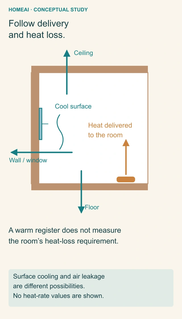
The outside wall, window, ceiling and floor form part of the room’s heat-loss picture. A bedroom over an unheated garage, a corner room and an interior room have different surroundings. Their required heat delivery can differ even when the visible registers look alike. The room drawing puts incoming heat and the enclosure in the same view.
Follow delivery and heat loss.
Room supply, enclosure and cool surface. Comfort depends on delivery and the room’s surroundings. The arrows identify possible transfer routes without quantifying heat loss or diagnosing air leakage.
Explore the labelled parts
- Delivery
The amber register identifies a conceptual incoming heat-delivery route. Its warmth alone does not measure the volume of moving air or total heat delivered to this room.
- Enclosure
The wall, window, ceiling and floor have different surroundings in different homes. The teal arrows identify possible heat-transfer routes, not equal losses, calculated rates or a finding about a particular assembly.
- Cool surface
A cool window can affect radiant comfort and produce a cooling air current. That sensation does not by itself identify an air leak around the window. Enclosure air leakage is a separate assessment question.
- Combined assessment
The room can have delivery and enclosure issues together. Ask which finding the proposed distribution or enclosure work addresses, what remains outside scope and how heating and ventilation interactions will be considered.
Heat moves through materials, air movement carries heat, and warm and cool surfaces affect comfort. NRCan explains that a cold window can create a downward cooling air current as well as a radiant comfort difference. Feeling a draft near glass does not by itself show a hole around the window; air leakage is another possibility to investigate.
Wind-related discomfort can help focus an enclosure question, while a coldest-weather pattern may reveal a delivery or heat-loss shortfall. Neither pattern proves a single cause. The distribution provider and an appropriate building-envelope or energy-assessment professional may need complementary scopes rather than competing guesses.
Insulation and air sealing have different jobs, and ventilation still matters when the enclosure changes. Ask which location and mechanism a proposed enclosure repair addresses and how its relationship with heating and ventilation will be considered. Adding furnace capacity without understanding the room can leave the original weak path or cold surface unchanged.
Follow delivery and heat loss.
Room supply, enclosure and cool surface. Comfort depends on delivery and the room’s surroundings. The arrows identify possible transfer routes without quantifying heat loss or diagnosing air leakage.
- Delivery
- The amber register identifies a conceptual incoming heat-delivery route. Its warmth alone does not measure the volume of moving air or total heat delivered to this room.
- Enclosure
- The wall, window, ceiling and floor have different surroundings in different homes. The teal arrows identify possible heat-transfer routes, not equal losses, calculated rates or a finding about a particular assembly.
- Cool surface
- A cool window can affect radiant comfort and produce a cooling air current. That sensation does not by itself identify an air leak around the window. Enclosure air leakage is a separate assessment question.
- Combined assessment
- The room can have delivery and enclosure issues together. Ask which finding the proposed distribution or enclosure work addresses, what remains outside scope and how heating and ventilation interactions will be considered.
Read all the diagram text
- HOMEAI · CONCEPTUAL STUDY
- Follow delivery and heat loss.
- Heat delivered to the room
- Ceiling
- Wall / window
- Floor
- Cool surface
- A warm register does not measure the room’s heat-loss requirement.
- Surface cooling and air leakage are different possibilities. No heat-rate values are shown.
Sources for this chapter
The thermostat speaks for its own location
A central thermostat responds to the temperature around its sensor and the selected controls. It does not directly measure every bedroom. A comfortable hall can satisfy the heating call while another room responds differently. Start by recording what the display actually says: mode, setpoint, displayed temperature and any schedule or override you recognize.
A running fan does not necessarily mean heat is being added at that moment. Heating, cooling and fan-only operation have different meanings, and equipment may have its own sequences. Use the actual controls guide or ask the provider to explain the indication. Do not infer a failed heater from the sound of a fan alone.
Keep the control record simple before changing settings. Note an unfamiliar override, a recent thermostat replacement or a change in the rooms people occupy. A provider can check whether the controls suit the equipment and whether operating settings match the intended system. The thermostat-performance guide goes further into schedules and a useful operating log.
Continuous fan operation can redistribute household air, but it does not create an outdoor-air ventilation system or guarantee a balanced room. Likewise, raising the setpoint to satisfy one bedroom can make other areas uncomfortable. Ask how a proposed control change addresses the measured problem and what trade-offs remain.
Sources for this chapter
Make a short, comparable comfort record
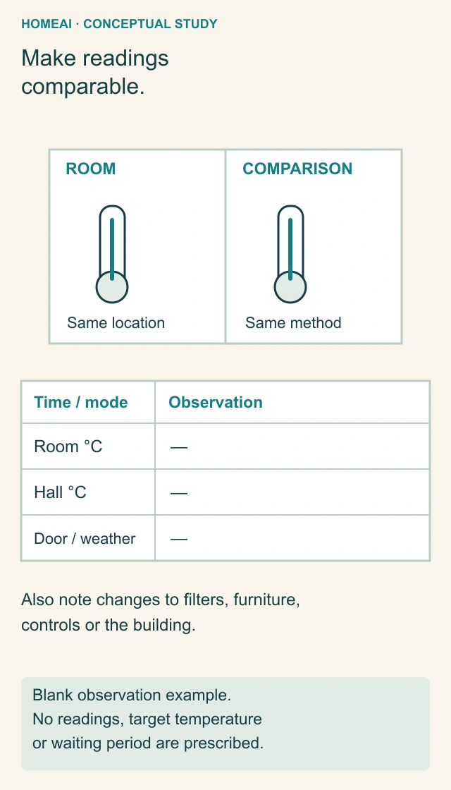
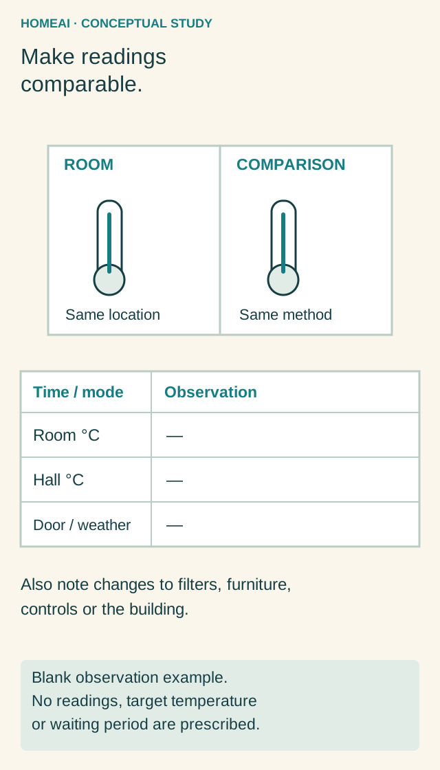
The comfort record keeps the room and the circumstances beside each observation. Identify the affected room and an ordinary comparison location, such as the hall. Use the same thermometer and consistent positions away from direct sun and supply jets. Write down its location so a later reading means the same thing.
Make readings comparable.
Room and comparison readings. Consistent locations and operating context make a comfort account easier to interpret. The table is blank and provides neither a diagnosis nor a required waiting period.
Explore the labelled parts
- Consistent locations
Use the same thermometer and consistent positions away from direct sun and supply jets. Record where it was placed so later readings can be compared sensibly. This is an ordinary comfort observation, not a calibrated capacity test.
- Operating context
Record time, actual heating or fan mode, thermostat indication, ordinary door position and outdoor conditions. A heating reading and a fan-only reading should not silently become equivalent operating conditions.
- Change history
Note relevant filter, furniture, schedule, equipment or renovation changes and when they occurred. Several simultaneous changes make cause attribution difficult; preserve what is known and unknown.
- Limits and urgency
The blank Celsius fields are prompts, not readings or temperature targets. No log duration is required. Seek appropriate assistance for loss of heat, vulnerability to cold or any safety concern rather than waiting for an ideal record.
Record the time, outdoor conditions, heating mode, displayed thermostat information and ordinary door position. Note whether other rooms share the pattern and whether a grille is obstructed. A reading during heating and one during fan-only operation should not silently become a like-for-like equipment comparison.
Keep an account of changes: furniture moved, a specified filter replaced, a schedule changed or a renovation completed. Avoid changing several things at once and then assigning the result to the one you preferred. Report the timing accurately, including when you cannot tell which change mattered.
This record helps describe the complaint and plan an assessment. It does not measure duct pressure, room airflow or heating capacity. You need not keep waiting for a perfect log when the home is losing heat, someone is vulnerable to cold, or a safety concern appears. Seek appropriate assistance for the conditions actually present.
Make readings comparable.
Room and comparison readings. Consistent locations and operating context make a comfort account easier to interpret. The table is blank and provides neither a diagnosis nor a required waiting period.
- Consistent locations
- Use the same thermometer and consistent positions away from direct sun and supply jets. Record where it was placed so later readings can be compared sensibly. This is an ordinary comfort observation, not a calibrated capacity test.
- Operating context
- Record time, actual heating or fan mode, thermostat indication, ordinary door position and outdoor conditions. A heating reading and a fan-only reading should not silently become equivalent operating conditions.
- Change history
- Note relevant filter, furniture, schedule, equipment or renovation changes and when they occurred. Several simultaneous changes make cause attribution difficult; preserve what is known and unknown.
- Limits and urgency
- The blank Celsius fields are prompts, not readings or temperature targets. No log duration is required. Seek appropriate assistance for loss of heat, vulnerability to cold or any safety concern rather than waiting for an ideal record.
Read all the diagram text
- HOMEAI · CONCEPTUAL STUDY
- Make readings comparable.
- ROOM
- COMPARISON
- Same location
- Same method
- Time / mode
- Observation
- Room °C
- Hall °C
- Door / weather
- —
- Also note changes to filters, furniture, controls or the building.
- Blank observation example. No readings, target temperature or waiting period are prescribed.
Sources for this chapter
Keep ordinary observations separate from service work
Homeowner observation can include reading the external control display, noting accessible grilles and following the actual manual’s identified filter procedure. Keep hands, tools and cameras out of blower compartments, electrical spaces and duct openings. Do not remove gas or vent connections, bypass safety devices or repeatedly reset a system that stops.
Do not create an airflow test with smoke, incense, blocked registers or improvised pressure tubing. Those actions can introduce hazards or change the system you are trying to understand. Record an unusual noise, visible error indication or loss of heating from a safe ordinary position and give it to the appropriate service provider.
A carbon monoxide alarm is an emergency, not a room-comfort experiment. Health Canada directs occupants to leave immediately for fresh air, avoid searching for the source, and call 911 or local emergency services from outside. Return only after a professional has fixed the problem. A normal-looking furnace cabinet does not override the alarm.
If you smell gas, follow the local gas utility’s emergency instructions and seek help from outside rather than investigating equipment. The scoped furnace manual also treats a gas odour as a reason to leave and obtain emergency assistance. Never continue a comfort log to decide whether a potential fuel or combustion hazard is real.
Sources for this chapter
Ask for measurements that answer different questions
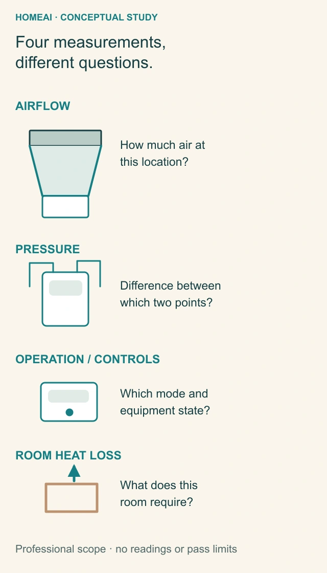
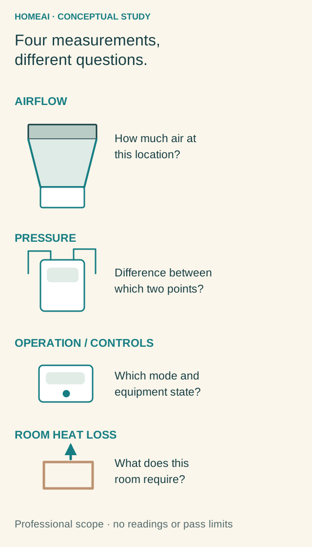
A room-comfort assessment can need more than a routine equipment service. Ask the provider what the visit includes before assuming every duct and exterior wall will be evaluated. The measurement drawing separates four jobs: room airflow, system pressure, equipment and control operation, and the room’s heat-loss requirement.
Four measurements, different questions.
Airflow, pressure, controls and room heat loss. Different assessments answer different questions. Ask for the locations, operating conditions and scope rather than treating one reading as a whole-system verdict.
Explore the labelled parts
- Airflow
A professional airflow measurement concerns moving air at the named location and operating conditions. The hood symbol identifies that measurement job and supplies no homeowner procedure, measured flow or universal pass value.
- Pressure
A pressure reading is a difference between identified locations or a stated reference. The instrument symbol has two reference leads, no connection to gas equipment and no reading. Ask how the measured difference relates to the finding.
- Operation and controls
The assessor can identify the actual heating, cooling or fan state and examine controls and equipment within the agreed service scope. A fan sound or a thermostat display alone does not establish every component’s operation.
- Room heat loss
A room-by-room load assessment concerns the room’s required heat delivery under stated assumptions. This is separate from a register temperature or routine furnace maintenance. Distribution and enclosure expertise may have complementary roles.
An airflow reading concerns a quantity of moving air at the stated location and operating conditions. A pressure reading concerns a difference between identified locations or references. A temperature reading concerns its sensor location and time. Ask the report to identify what was measured and how the result relates to the complaint.
A room-by-room load assessment asks how much heat the rooms need under its design assumptions. It is a different exercise from checking whether a burner or fan operates. A contractor may need existing drawings, equipment information, access and observations; a complementary enclosure assessment may be appropriate when the distribution findings do not explain everything.
Keep findings and unassessed questions separate. A report can establish a branch problem while leaving an exterior-wall question open. Ask which proposed change follows from which finding, what remains outside the scope and how improvement will be checked. You should be able to understand the reason for the work without becoming the person who performs the tests.
Four measurements, different questions.
Airflow, pressure, controls and room heat loss. Different assessments answer different questions. Ask for the locations, operating conditions and scope rather than treating one reading as a whole-system verdict.
- Airflow
- A professional airflow measurement concerns moving air at the named location and operating conditions. The hood symbol identifies that measurement job and supplies no homeowner procedure, measured flow or universal pass value.
- Pressure
- A pressure reading is a difference between identified locations or a stated reference. The instrument symbol has two reference leads, no connection to gas equipment and no reading. Ask how the measured difference relates to the finding.
- Operation and controls
- The assessor can identify the actual heating, cooling or fan state and examine controls and equipment within the agreed service scope. A fan sound or a thermostat display alone does not establish every component’s operation.
- Room heat loss
- A room-by-room load assessment concerns the room’s required heat delivery under stated assumptions. This is separate from a register temperature or routine furnace maintenance. Distribution and enclosure expertise may have complementary roles.
Read all the diagram text
- HOMEAI · CONCEPTUAL STUDY
- Four measurements, different questions.
- AIRFLOW
- How much air at this location?
- PRESSURE
- Difference between which two points?
- OPERATION / CONTROLS
- Which mode and equipment state?
- ROOM HEAT LOSS
- What does this room require?
- Professional scope · no readings or pass limits
Sources for this chapter
Compare repairs by the mechanism they change
Correct maintenance and compatible filtration address equipment care and a particular resistance or fit issue. They are often a different scope from duct reconstruction. Their limitation is straightforward: a correct filter does not enlarge an inadequate branch or create a missing room return path. Preserve the specification and service description so later visits start from the actual configuration.
Duct connection repairs, suitable sealing and professional balancing address identified distribution conditions. Access can involve finished areas, and a change to one branch can affect others. Ask which connections and rooms are included, what restoration is included and how the final system will be assessed. Duct cleaning alone does not establish that these tasks were done.
A designed return-path alteration addresses how air leaves a room when its door is in the intended position. It can involve ducts or transfer arrangements, each with construction and room-use implications. Ask about the complete design and local requirements instead of comparing only the price of a grille or assuming a larger door gap is acceptable.
Control changes and enclosure work address other sides of the comfort problem. Controls can change when heat is called for; enclosure work can change the loss or cold-surface condition. Each proposal should state its target and its limits. Equipment replacement needs its own sizing and integration case; a larger heat source is not a universal repair for an unmeasured cold room.
Sources for this chapter
Leave with a clear proposal and a useful next question
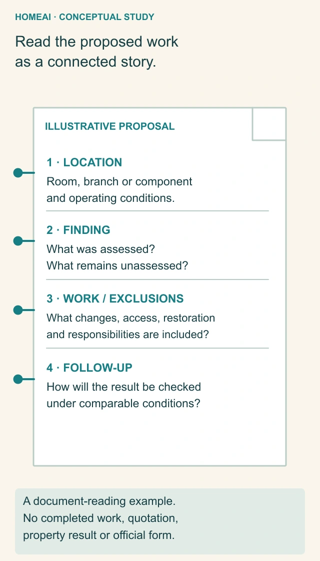
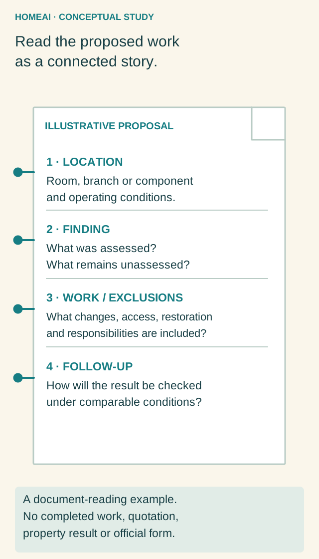
The annotated proposal helps you compare work on the same terms. Name the actual room, route or component; state the finding and its operating conditions; describe the work and exclusions; and identify the agreed follow-up. That makes a filter task, a branch repair and an enclosure investigation easier to compare.
Read the proposed work as a connected story.
Location, finding, proposed work and follow-up. A clear scope explains what the repair changes and what remains outside it. This is an original reading aid, not a completed service record or quotation.
Explore the labelled parts
- Location and conditions
Identify the actual room, branch or component and the operating conditions relevant to the complaint. A whole-home claim should not silently replace a finding from one room or accessible connection.
- Finding and remaining questions
Ask what was assessed, what was found and what remains outside the visit. A confirmed distribution issue can coexist with an enclosure question that needs a different scope.
- Work and exclusions
Describe the mechanism the work changes, access, restoration, responsibilities and exclusions. Filter maintenance, duct repairs, return-path design, controls and enclosure work are different deliverables.
- Follow-up
Agree how the result will be checked under comparable conditions and keep the actual service record. No specified outcome, price, named homeowner, completed repair or official approval is provided in this illustration.
Ask the provider to explain one chain in plain language: what was found, how that affects this room, what the work changes and how the result will be checked. If the answer jumps from a warm register to a new furnace without explaining delivery and loss, ask for the missing assessment rather than choosing equipment by guesswork.
Keep the original service record, model information and any drawings supplied with completed work. If the room becomes more comfortable, note the weather and operating conditions too. That record helps you understand what improved and gives a later service visit a useful starting point.
Read the proposed work as a connected story.
Location, finding, proposed work and follow-up. A clear scope explains what the repair changes and what remains outside it. This is an original reading aid, not a completed service record or quotation.
- Location and conditions
- Identify the actual room, branch or component and the operating conditions relevant to the complaint. A whole-home claim should not silently replace a finding from one room or accessible connection.
- Finding and remaining questions
- Ask what was assessed, what was found and what remains outside the visit. A confirmed distribution issue can coexist with an enclosure question that needs a different scope.
- Work and exclusions
- Describe the mechanism the work changes, access, restoration, responsibilities and exclusions. Filter maintenance, duct repairs, return-path design, controls and enclosure work are different deliverables.
- Follow-up
- Agree how the result will be checked under comparable conditions and keep the actual service record. No specified outcome, price, named homeowner, completed repair or official approval is provided in this illustration.
Read all the diagram text
- HOMEAI · CONCEPTUAL STUDY
- Read the proposed work as a connected story.
- ILLUSTRATIVE PROPOSAL
- 1 · LOCATION
- Room, branch or component and operating conditions.
- 2 · FINDING
- What was assessed? What remains unassessed?
- 3 · WORK / EXCLUSIONS
- What changes, access, restoration and responsibilities are included?
- 4 · FOLLOW-UP
- How will the result be checked under comparable conditions?
- A document-reading example. No completed work, quotation, property result or official form.
Sources for this chapter
Keep learning about the connected parts
- Furnace filters: filtration and airflow must work together
- Thermostat settings: read the control before comparing comfort
- Hydronic heating: record the zone before blaming the boiler
- Electric heated floors: understand the heater, sensor and response
- How a heat pump moves heat: the cycle, rooms and energy numbers
- HRVs and ERVs explained: fresh air, heat recovery and useful maintenance
- Portable space heaters: follow the heat, controls and supply
Canadian context and authorities · Visual atlas · Learning labs
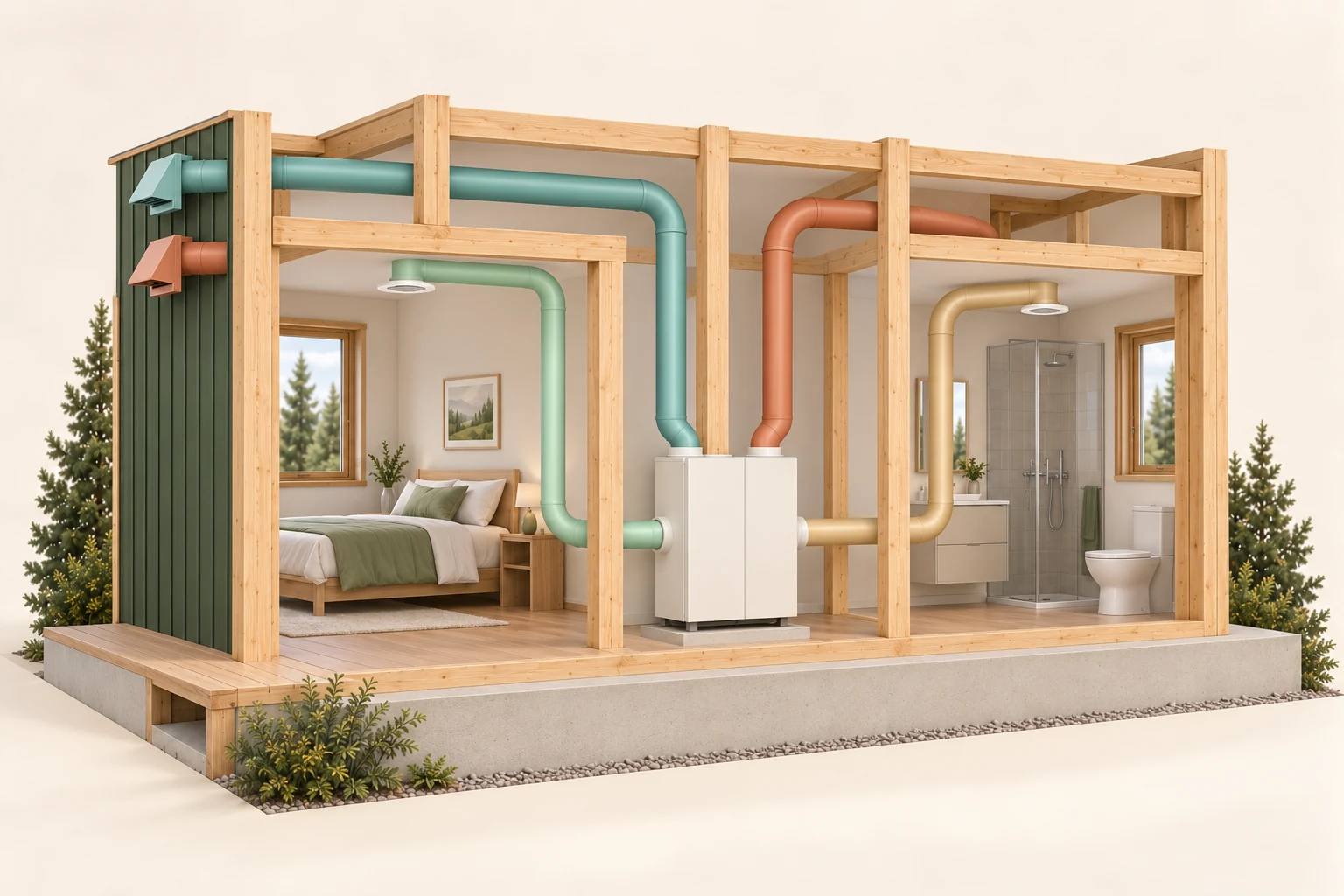
Outdoor and indoor routes meet at the equipment.
A closed ventilation cabinet with four separately coloured connections. Two outdoor hoods and two indoor grilles in an open timber-frame room model. Separate conceptual outdoor and indoor routes; part of an outdoor run passes behind framing.
The evidence the illustration cannot supply
The equipment type, recovery performance and manufacturer port arrangement. Commissioned airflow, balancing, controls, duct sizing and appropriate outdoor-terminal separation. Filtration performance, indoor-air exposure and the actual routing in a home. This is a separate conceptual teaching house, not another view of a surveyed property.
Know the parts.
Know what the words mean.
- Distribution assessment
- A scoped evaluation of how conditioned air or heat reaches and leaves intended spaces.
- Room response
- The observed temperature or comfort change under stated operating conditions.
- Supply branch
- A duct route carrying conditioned air from a shared supply trunk toward a room.
- Return path
- The available route by which household air travels from an occupied room back toward a circulating blower.
- Register boot
- The duct fitting connecting a branch duct to its room outlet opening.
- Circulating blower
- The fan that moves household air through the equipment and connected distribution system.
- Room heat loss
- The heat leaving a room through its enclosure and air exchange under stated conditions.
- Pressure difference
- The pressure at one identified location compared with another reference location.
Questions to bring
to the conversation.
- Which system and supply/return route serve this actual room?
- Does the pattern change with ordinary door position, weather or operating mode?
- What airflow, pressure, control or heat-loss assessment supports the proposed work?
- What will be changed, what remains outside scope and how will improvement be checked?
Separate a showing observation, an existing record and a new professional assessment. Unknown means a question remains; it does not automatically mean a defect.
Use the evidence planner ↗Go to the source.
Original HomeAI explanation informed by these public references. Sources support the underlying guidance; they have not reviewed or endorsed HomeAI. Diagrams are conceptual, and calculator outputs depend on your inputs.
Canadian room-comfort education. NRCan and Health Canada provide Canadian context; the identified US building-science explanations and named furnace manual illustrate specific mechanisms. Actual equipment, local requirements, access and professional assessment determine the work.
Publication & source review
First published .
Sources reviewed .
- Natural Resources Canada · How your house works
- City of Calgary · Home maintenance
- Natural Resources Canada · Heating and cooling with a heat pump
- Natural Resources Canada · Operating heating and ventilation
- Health Canada · Ventilation and the indoor environment
- Natural Resources Canada · Preparing for an EnerGuide evaluation
- Natural Resources Canada · Keeping the Heat In, Section 2: How your house works
- Natural Resources Canada · Keeping the Heat In, Section 9: Operating your house
- Health Canada · Ventilation and the indoor environment
- PNNL / US Department of Energy · Pressure balancing bedrooms
- PNNL / US Department of Energy · Building Science Introduction: Air Flow
- Carrier · OM8GFSUC-02 owner manual
- Natural Resources Canada · Heating and cooling with a heat pump
- Health Canada · Carbon monoxide: Preventing exposure
Have a question about your home?
Start with the symptom, timing and what you have observed.
Ask HomeAI